Tuesday, August 28, 2018
Monday, August 20, 2018
How to make Darkness Sensor Circuit| Light Sensor Circuit| Simple LDR Ci...
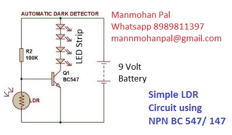
Darkness Sensor Circuit| Light Sensor Circuit| Simple LDR Circuit -by Manmohan Pal
This is a simple Darkness sensor circuit made by using a single NPN transistor BC 147/547 and a LDR with one 100 K Resistor,
The circuit can be used to make Automatic street lights, Automatic car headlights, Automatic Garden lights etc.
Circuit Diagram:
http://electronics4ubymanmohanpal.blogspot.com/2018/08/darkness-sensor-circuit.html

Components required to make a Simple LDR circuit are
NPN Transistor BC 147/547
LDR
100 K Resistor
12 Volt LED Strip
9 Volt Battery
Battery Connector
Subscrib My Youtube Channel To learn About Basic Electronics
https://www.youtube.com/channel/UCDnhARnHOEIPuNIEp5vPdGQ
https://www.youtube.com/watch?v=RcKvmXFsFuwhttps://www.youtube.com/watch?v=RcKvmXFsFuYYfkdsf Manmohan Pal WhatsApp 8989811397 mannmohanpal@gmail.com
Twitter: @ManmohanPal15
FaceBook Page: https://www.youtube.com/watch?v=RcKvmXFsFuw&t=242s
Blog: http://electronics4ubymanmohanpal.blogspot.com/2018/08/what-is-resistor.html
LED Flasher Circuit
http://electronics4ubymanmohanpal.blogspot.com/p/led-flasher-using-transistors-only.html
Dark Sensor Circuit
http://electronics4ubymanmohanpal.blogspot.com/2018/08/darkness-sensor-circuit.html
Remote Control ON/OFF Switch
IR LED emits infrared light, and used in TV remotes. This Infrared is received by the receiver TSOP17XX (TSOP 1738used in TV). TSOP17XX receives the modulated Infrared waves and changes its output. TSOP is available in many frequency ranges like TSOP1730, TSOP1738, TSOP1740 etc. Last two digits represent the frequency (in Khz) of modulated IR rays, on which TSOP responds. Like for example TSOP1738 reacts when it receives the IR radiation modulated at 38Khz. TSOP output is active low, means it becomes LOW when IR is detected.
In this remote controlled switch circuit we are using TV remote to ON/OFF the AC light by pressing any button of remote, and using the TSOP1738 at receiver end. Receiver circuit is connected to AC appliance via Relay, so that we can control the light remotely. We have used IC 4017 to convert it into a push ON, push OFF switch. Go through this article to understand the IR Transmitter and Receiver.
Normally when we press any button of TV/DVD player remote, Light glows and as soon as we release Button, it becomes OFF. Now it can be converted into a PUSH ON and PUSH OFF toggle switch using IC CD4017. IC CD4017 is a CMOS decade counter IC. It can produce output at the 10 pins sequentially, i.e. it produces output one by one at the 10 output pins. Output is switched to one pin to another by applying a clock pulse at pin 14. Learn more about IC 4017 here.
remote control switch

When firstly, power is applied to IC 4017, output at PIN 3 (Q0) is HIGH, when we press the button of IR remote, then a LOW to HIGH clock pulse is applied to PIN 14 (first clock pulse) and output at Q0 becomes low and PIN 2(Q1) becomes HIGH. PIN 2 triggers the RELAY module, and the AC light becomes ON. Now this position will remain until the next clock pulse. If we press the Button of IR remote again (second clock pulse), output at Q1 becomes LOW and Q2 becomes HIGH. This will deactivate the Relay and switch off the light. And because Q2 is connected to the RESET pin 15 of 4017, it will reset the IC and again output at Q0 becomes HIGH and Q2 becomes LOW (initial state). So it works like a toggle switch.
Output of TSOP1738 oscillates at the rate of 38KHz, which is applied to clock pulse of 4017. So we have connected a 1uF capacitor across the output of the TSOP so that this 38KHz pulse train is counted as one clock pulse to the IC 4017.
Video Link
We can also use the IR transmitter circuit to ON/OFF the Bulb, this IR transmitter circuit produces modulated IR at 38KHz like a TV remote. Also we can replace Bulb with any AC appliance, which is to be controlled by remote control.
Circuit Diagram
https://drive.google.com/open?id=19LMxDXTuDkb0W8pfx1JZW4kMqenVtAhJ
Manmohan Pal
Mob. 8989811397
Email- mannmohanpal@gmail.com
Blog: http://electronics4ubymanmohanpal.blogspot.in/p/blog-page_5.html
Youtube Channel: https://www.youtube.com/channel/UCDnhARnHOEIPuNIEp5vPdGQ
Remote control for every home appliance
https://www.youtube.com/watch?v=mUuSYWyD7Ic
Remote operated light- by Manmohan Pal
https://www.youtube.com/watch?v=5oP1SCkVJm8
Remote control Fan- IR remote control Circuit using IC 555 Timer by Manmohan Pal
https://www.youtube.com/watch?v=GvAZadfdIAE
Remote control Light Switch
https://manmohanpal.wordpress.com/2018/05/06/remote-control-circuit/
Remote control for every home appliance
Remote control switch
http://electronics4ubymanmohanpal.blogspot.in/p/remote-control-switch.html
Remote Control On Off Switch
Remote control switch
Remote Controlled Light Switch
IR LED emits infrared light, and used in TV remotes. This Infrared is received by the receiver TSOP17XX (TSOP 1738used in TV). TSOP17XX receives the modulated Infrared waves and changes its output. TSOP is available in many frequency ranges like TSOP1730, TSOP1738, TSOP1740 etc. Last two digits represent the frequency (in Khz) of modulated IR rays, on which TSOP responds. Like for example TSOP1738 reacts when it receives the IR radiation modulated at 38Khz. TSOP output is active low, means it becomes LOW when IR is detected.
In this remote controlled switch circuit we are using TV remote to ON/OFF the AC light by pressing any button of remote, and using the TSOP1738 at receiver end. Receiver circuit is connected to AC appliance via Relay, so that we can control the light remotely. We have used IC 4017 to convert it into a push ON, push OFF switch. Go through this article to understand the IR Transmitter and Receiver.
Normally when we press any button of TV/DVD player remote, Light glows and as soon as we release Button, it becomes OFF. Now it can be converted into a PUSH ON and PUSH OFF toggle switch using IC CD4017. IC CD4017 is a CMOS decade counter IC. It can produce output at the 10 pins sequentially, i.e. it produces output one by one at the 10 output pins. Output is switched to one pin to another by applying a clock pulse at pin 14. Learn more about IC 4017 here.
remote control switch

When firstly, power is applied to IC 4017, output at PIN 3 (Q0) is HIGH, when we press the button of IR remote, then a LOW to HIGH clock pulse is applied to PIN 14 (first clock pulse) and output at Q0 becomes low and PIN 2(Q1) becomes HIGH. PIN 2 triggers the RELAY module, and the AC light becomes ON. Now this position will remain until the next clock pulse. If we press the Button of IR remote again (second clock pulse), output at Q1 becomes LOW and Q2 becomes HIGH. This will deactivate the Relay and switch off the light. And because Q2 is connected to the RESET pin 15 of 4017, it will reset the IC and again output at Q0 becomes HIGH and Q2 becomes LOW (initial state). So it works like a toggle switch.
Output of TSOP1738 oscillates at the rate of 38KHz, which is applied to clock pulse of 4017. So we have connected a 1uF capacitor across the output of the TSOP so that this 38KHz pulse train is counted as one clock pulse to the IC 4017.
Video Link
We can also use the IR transmitter circuit to ON/OFF the Bulb, this IR transmitter circuit produces modulated IR at 38KHz like a TV remote. Also we can replace Bulb with any AC appliance, which is to be controlled by remote control.
Circuit Diagram
https://drive.google.com/open?id=19LMxDXTuDkb0W8pfx1JZW4kMqenVtAhJ
Manmohan Pal
Mob. 8989811397
Email- mannmohanpal@gmail.com
Blog: http://electronics4ubymanmohanpal.blogspot.in/p/blog-page_5.html
Youtube Channel: https://www.youtube.com/channel/UCDnhARnHOEIPuNIEp5vPdGQ
Remote control for every home appliance
https://www.youtube.com/watch?v=mUuSYWyD7Ic
Remote operated light- by Manmohan Pal
https://www.youtube.com/watch?v=5oP1SCkVJm8
Remote control Fan- IR remote control Circuit using IC 555 Timer by Manmohan Pal
https://www.youtube.com/watch?v=GvAZadfdIAE
Remote control Light Switch
https://manmohanpal.wordpress.com/2018/05/06/remote-control-circuit/
Remote control for every home appliance
Remote control switch
http://electronics4ubymanmohanpal.blogspot.in/p/remote-control-switch.html
Remote Controlled Light Switch
IR LED emits infrared light, and used in TV remotes. This Infrared is received by the receiver TSOP17XX (TSOP 1738used in TV). TSOP17XX receives the modulated Infrared waves and changes its output. TSOP is available in many frequency ranges like TSOP1730, TSOP1738, TSOP1740 etc. Last two digits represent the frequency (in Khz) of modulated IR rays, on which TSOP responds. Like for example TSOP1738 reacts when it receives the IR radiation modulated at 38Khz. TSOP output is active low, means it becomes LOW when IR is detected.
In this remote controlled switch circuit we are using TV remote to ON/OFF the AC light by pressing any button of remote, and using the TSOP1738 at receiver end. Receiver circuit is connected to AC appliance via Relay, so that we can control the light remotely. We have used IC 4017 to convert it into a push ON, push OFF switch. Go through this article to understand the IR Transmitter and Receiver.
Normally when we press any button of TV/DVD player remote, Light glows and as soon as we release Button, it becomes OFF. Now it can be converted into a PUSH ON and PUSH OFF toggle switch using IC CD4017. IC CD4017 is a CMOS decade counter IC. It can produce output at the 10 pins sequentially, i.e. it produces output one by one at the 10 output pins. Output is switched to one pin to another by applying a clock pulse at pin 14. Learn more about IC 4017 here.
remote control switch
When firstly, power is applied to IC 4017, output at PIN 3 (Q0) is HIGH, when we press the button of IR remote, then a LOW to HIGH clock pulse is applied to PIN 14 (first clock pulse) and output at Q0 becomes low and PIN 2(Q1) becomes HIGH. PIN 2 triggers the RELAY module, and the AC light becomes ON. Now this position will remain until the next clock pulse. If we press the Button of IR remote again (second clock pulse), output at Q1 becomes LOW and Q2 becomes HIGH. This will deactivate the Relay and switch off the light. And because Q2 is connected to the RESET pin 15 of 4017, it will reset the IC and again output at Q0 becomes HIGH and Q2 becomes LOW (initial state). So it works like a toggle switch.
Output of TSOP1738 oscillates at the rate of 38KHz, which is applied to clock pulse of 4017. So we have connected a 1uF capacitor across the output of the TSOP so that this 38KHz pulse train is counted as one clock pulse to the IC 4017.
Video Link
We can also use the IR transmitter circuit to ON/OFF the Bulb, this IR transmitter circuit produces modulated IR at 38KHz like a TV remote. Also we can replace Bulb with any AC appliance, which is to be controlled by remote control.
Circuit Diagram
https://drive.google.com/open?id=19LMxDXTuDkb0W8pfx1JZW4kMqenVtAhJ
Manmohan Pal
Mob. 8989811397
Email- mannmohanpal@gmail.com
Blog: http://electronics4ubymanmohanpal.blogspot.in/p/blog-page_5.html
Youtube Channel: https://www.youtube.com/channel/UCDnhARnHOEIPuNIEp5vPdGQ
Remote control for every home appliance
https://www.youtube.com/watch?v=mUuSYWyD7Ic
Remote operated light- by Manmohan Pal
https://www.youtube.com/watch?v=5oP1SCkVJm8
Remote control Fan- IR remote control Circuit using IC 555 Timer by Manmohan Pal
https://www.youtube.com/watch?v=GvAZadfdIAE
Remote control Light Switch
https://manmohanpal.wordpress.com/2018/05/06/remote-control-circuit/
Remote control for every home appliance
Remote control switch
http://electronics4ubymanmohanpal.blogspot.in/p/remote-control-switch.html
Darkness sensor circuit
Darkness Sensor Circuit| Light Sensor Circuit| Simple LDR Circuit -by Manmohan Pal
This is a simple Darkness sensor circuit made by using a single NPN transistor BC 147/547 and a LDR with one 100 K Resistor,
The circuit can be used to make Automatic street lights, Automatic car headlights, Automatic Garden lights etc.
Circuit Diagram:
http://electronics4ubymanmohanpal.blogspot.com/2018/08/darkness-sensor-circuit.html
Components required to make a Simple LDR circuit are
NPN Transistor BC 147/547
LDR
100 K Resistor
12 Volt LED Strip
9 Volt Battery
Battery Connector
Subscrib My Youtube Channel To learn About Basic Electronics
https://www.youtube.com/channel/UCDnhARnHOEIPuNIEp5vPdGQ
https://www.youtube.com/watch?v=RcKvmXFsFuwhttps://www.youtube.com/watch?v=RcKvmXFsFuYYfkdsf Manmohan Pal WhatsApp 8989811397 mannmohanpal@gmail.com
Twitter: @ManmohanPal15
FaceBook Page: https://www.youtube.com/watch?v=RcKvmXFsFuw&t=242s
Blog: http://electronics4ubymanmohanpal.blogspot.com/2018/08/what-is-resistor.html
LED Flasher Circuit
http://electronics4ubymanmohanpal.blogspot.com/p/led-flasher-using-transistors-only.html
Dark Sensor Circuit
http://electronics4ubymanmohanpal.blogspot.com/2018/08/darkness-sensor-circuit.html
Tuesday, August 14, 2018
Friday, August 10, 2018
What is Resistor ?
What is Resistor ?

A resistor is a passive two-terminal electrical component and its primary function is to limit the flow of electric current.
A resistor is a passive two-terminal electrical component that implements electrical resistance as a circuit element. In electronic circuits, resistors are used to reduce current flow, adjust signal levels, to divide voltages, bias active elements, and terminate transmission lines, among other uses. High-power resistors that can dissipate many watts of electrical power as heat, may be used as part of motor controls, in power distribution systems, or as test loads for generators. Fixed resistors have resistances that only change slightly with temperature, time or operating voltage. Variable resistors can be used to adjust circuit elements (such as a volume control or a lamp dimmer), or as sensing devices for heat, light, humidity, force, or chemical activity.
Youtube Video Link Video Link
Subscrib My Youtube Channel To learn About Basic Electronics
https://www.youtube.com/channel/UCDnhARnHOEIPuNIEp5vPdGQ
https://www.youtube.com/watch?v=RcKvmXFsFuwhttps://www.youtube.com/watch?v=RcKvmXFsFuYYfkdsf Manmohan Pal WhatsApp 8989811397 mannmohanpal@gmail.com
Twitter: @ManmohanPal15
FaceBook Page: https://www.youtube.com/watch?v=RcKvmXFsFuw&t=242s
Blog: http://electronics4ubymanmohanpal.blogspot.com/2018/08/what-is-resistor.html
Subscribe to:
Posts (Atom)